A New Theory for Preparing Models in Order to Analyse Engineering Structures
D. Simoes and Prof. T. A. Jadhav (both affiliated with Sinhgad College, Pune)
Abstract
In this paper, a new theory for preparing models by using 'finite elements' is described, in which the integration is performed at the corner points of the element, instead of points in the interior. A user subroutine (UEL) in the Fortran programming language was written in order to test a new formulation in the finite element software Abaqus. Some test cases were analysed and the results were presented.
1. Introduction
I shall begin by explaining how the technique that is known as the 'Finite Element Method' (FEM) was invented years ago:
Figure 1. The invention of FEM
Figure 1 contains an accurate description of FEM, except that I did not invent it.
The way in the equations for calculating the stresses and displacements in an element (i.e. a single rectangle, in this case) are written and simplified is called as the 'finite element formulation'
Ever since research into finite element formulations began in the 1970s, the numerical integration (remember your calculus?) has been performed at some points in the interior of the element, because it's easier that way. However, performing the integration at the corners of the element (called 'nodes') has some advantages of its own and the first descriptions about this approach have been around since around 2000.
There's this awesome software called Abaqus that solves problems based on FEM. It contains element formulations already coded in. In case you're finding life boring and are not satisfied with the mundane, there's a feature known as the 'User ELement' or UEL, that lets you code your own element formulation and make Abaqus use it.
Figure 2. Sometimes when you are bored, one does something challenging, like writing an Abaqus UEL
In this paper we describe a formulation proposed by two awesome-sauce researchers, G. Castellazzi and P. Krysl. We then implement a new type of element, somewhat based on this approach, in Abaqus by writing a user subroutine (UEL).
2. Element formulation
After a series of several mind-bending-extremely-complex-equations-that-I-find-difficult-to-understand-myself, we arrive at
Figure 3 explains the indices:
Figure 3. Nodal patch illustrated for various mesh configurations
This, simply put, says that it is possible to approximate the strain at a node, by the weighted average of the strains of all the elements connected to that node, not without a few caveats, disclaimers and exceptions.
3. Abaqus implementation
At this interesting stage, I raise the stakes and put on my programmer's hat above my FEM hat (did you notice the watermelon above the gas cylinder in figure 2?).
We made several approximations and simplifications in the element formulation to get around the limitations of the Abaqus UEL, and write a FORTRAN code for the element formulation. We then prepared two simple FEM models (figures 4 and 5) and used these two as guinea pigs to try out the element formulation.
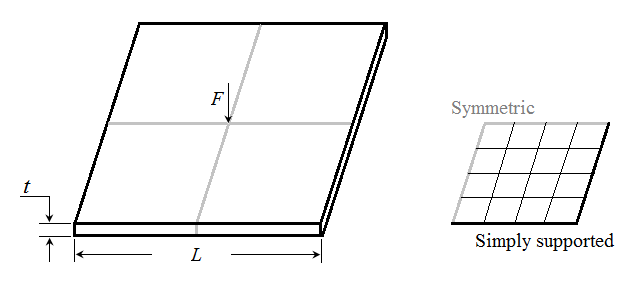
Figure 4. Simply supported plate with concentrated load
Figure 5. Clamped strip
4. Results
The table below shows the comparison between the results obtained in the two FEM models using the known formulae for the exact value of the displacement, the inbuilt element formulation in Abaqus, and the formulation that we coded in the UEL.
Table 1. Displacement results of test cases
Test case
|
Exact displacement
|
Abaqus inbuilt elements
|
New formulation UEL
|
Figure 5. Simply supported plate
|
0.021138
|
0.021502
|
0.014779
|
Figure 6. Clamped strip
|
29.468
|
28.894
|
24.224
|
5. Conclusion
As can be seen from the table, our code for the UEL formulation sucks. We would like to shift the blame to the the assumptions made in order to implement in Abaqus UEL, and due to the research being at an initial stage. What other researchers can learn from our mistakes is that Abaqus UEL is not suitable for implementing formulations that involve nodal integrations. To paraphrase Edison, we have not failed to implement this formulation accurately in Abaqus, but we have found one way that won't work. At least we have now learnt more about element formulations and Abaqus than we knew earlier.
Acknowledgements
We would like to thank the helpful people at Faurecia for permitting the use of their resources in order to run some of the simulations. We would also like to thank you, our families and friends who are always there for us. Science rocks, and praise God for that! :)